Calculator Filter Pi Lc

Butterworth Pi Lc Low Pass Filter Calculator Jotrin Electronics
Band Pass Filter Calculator Electronicbase

Ferrite Toroid Calculator Elektroniikka

Pin On الدوائر والمشاريع الالكترونية Electronic Circuit Project

8 Bit Digital To Analog Converter Dac Circuitos Uvas Audio

Pin On Programming And Computer Projects
This calculator helps determine the correct values of the inductance l and capacitance c of an inductor and capacitor to be used in a butterworth lc bandpass filter.
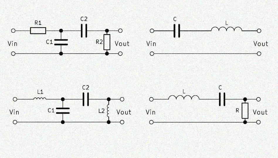
Calculator filter pi lc. High frequencies however should be as unhindered as possible. Lc high pass filter calculator general information about the high pass filter a high pass filter circuit designates a circuit in electrical engineering with the purpose of attenuating or blocking low frequencies. All that is needed is to input the desired cutoff frequency the passband the impedance and the ripple. A pi filter is a filter that has a series element and two parallel elements connected in the shape of the greek letter pi.
It can often be difficult to design a simple lc low pass filter as the calculations may be difficult to perform or tables of normalised values may not be available. I m trying to use a simple pi low pass filter using two capacitors and one inductor. Chebyshev filters are analog or digital filters having a steeper roll off and more passband ripple or stopband ripple than butterworth filters. I ve found the formula to calculate the value of the capacitance and of the inductance using the cut off frequency but i would like to know where this formula comes from i can t find any explanation on the internet.
This calculator will give you the circuit topology as well as the component values. Calculate lc filters circuit values with low pass high pass band pass or band stop response. Passive low pass 2nd order. It is possible to have up to 9 stages of lc pair for this calculator.
A pi filter is a filter that has a series element and two parallel elements connected in the shape of the greek letter pi. With the 2nd order low pass filter a coil is connected in series with a capacitor which is why this low pass is also referred to as lc low pass filter again the output voltage v out is tapped parallel to the capacitor. Select chebyshev elliptic butterworth or bessel filter type with filter order up to 20 and arbitrary input and output impedances. This tool helps you create a matching circuit so that optimal power transfer occurs between unmatched loads.
Although there are some filter calculators on the web the equations for a simple filter can be easy to handle and they give an insight into the workings of the filter. Butterworth filter are characterized by a constant gain flat response across the midband of the circuit and a 20 db per decade roll off rate for each pole contained in the circuit.

Passive Crossover Schematic Most Types Crossover Audio Passive

Circuit Diagram Of Clap Operated Remote Fan Switch Circuit

The Lm317t Is An Adjustable Voltage Regulator Which Is Capable Of

Pin On Circuit

Boolean Algebra Calculator Algebra Calculator Algebra Calculator

Different Configurations Of Transistors Common Emitter

Lm317 Low Dropout Regulator 5v 2a Using Tip41 Electronic

Build A Low Voltage Insulation Tester Electronic Schematics

8 Candidate Quiz Buzzer Circuit Using 8051 Microcontroller

Analog Vs Digital A Comparative Study Is More Effective With

Sencillo Receptor Fm

Tutorial Winding Toroids Turn Count Step 1 Feed The Wire

Signal Generator And Inverter Using Ne555 Timers Circuit Diagram

Double Layer Pcb Manufacture By Mohite Electronics Pvt Ltd Led
